Module 3: Electrical Fundamentals, Site Assessment & System Design
Module 3: Electrical Fundamentals, Site Assessment & System Design
24 sept. 2026
Module information | |
|---|---|
Audience | Applicants to the EcoStride Installation Partner Programme |
Study time | About 4 hours |
Units | 13 |
Assessment | Part 1, Segment 3 (10 questions) |
Prerequisites | Programme Guide; Modules 1 and 2 |
Materials | Basic calculator |
Introduction
Correct design and installation depend on understanding how electrical systems behave. This module covers the electrical principles, component characteristics, site assessment and sizing methods required to specify a safe and suitable solar and battery system. Each worked example should be reproduced with a calculator.
Learning outcomes
On completing this module, partners should be able to:
- Apply the relationships between voltage, current, resistance, power and energy;
- Distinguish between power (kW) and energy (kWh);
- Calculate voltage and current for series and parallel connections;
- Interpret a PV module datasheet and the effects of temperature, shading and soiling;
- Describe the function and key ratings of inverters, charge controllers and batteries;
- Identify the main system types;
- Conduct a site assessment and load analysis;
- Size an inverter, battery and PV array for a simple system;
- Verify that a string configuration is within an inverter's voltage limits;
- Explain cable selection and calculate voltage drop;
- Verify equipment compatibility.
3.1 Electrical quantities
Key points |
|---|
Voltage drives current; resistance opposes it. |
V = I × R and P = V × I are the basis of most calculations in this module. |
Resistance in a conductor or connection converts power into heat: P = I² × R. |
Quantity | Symbol | Unit |
|---|---|---|
Voltage | V | volt (V) |
Current | I | ampere (A) |
Resistance | R | ohm (Ω) |
Power | P | watt (W) |

Example 1. A 230 V appliance draws 8 A. P = 230 × 8 = 1,840 W.
Example 2. A 2,000 W kettle operates at 230 V. I = 2,000 ÷ 230 = 8.7 A.
At 230 V, each ampere corresponds to approximately 230 W. Results should be checked against this order of magnitude.
Example 3: heat at a poor connection. A battery lug with a resistance of 0.05 Ω carries 40 A. Heat produced = 40² × 0.05 = 80 W, concentrated in a single joint, with a voltage loss of 40 × 0.05 = 2 V. Because heat is proportional to the square of the current, doubling the current produces four times the heat. This is the mechanism by which loose terminals, poor crimps and undersized conductors cause fires.
3.2 Energy: kW and kWh
Key points |
|---|
Power (kW) is a rate; energy (kWh) is a quantity. |
Inverters are rated in kW; batteries and consumption are measured in kWh. |

Example. A 0.75 kW compressor runs for 6 hours: E = 0.75 × 6 = 4.5 kWh.
Confusion between kW and kWh is a common cause of mis-sized systems and customer misunderstanding. A request for "a 5 kW system" may refer to an inverter, a battery or an array, which are different quantities.
Battery capacity stated in ampere-hours is converted to energy as follows:

A 12 V, 100 Ah battery stores 12 × 100 ÷ 1,000 = 1.2 kWh.
3.3 AC and DC; single-phase and three-phase
Key points |
|---|
PV modules and batteries produce DC; buildings use AC. The inverter converts between them. |
Motors and similar loads require more apparent power (kVA) than real power (kW). |
Direct current (DC) flows in one direction and has positive and negative polarity. Alternating current (AC) reverses direction periodically; the Nigerian supply operates at 50 Hz.
Single-phase supplies have one line conductor and a neutral at approximately 230 V (240 V in older documentation) and serve most homes and small premises. Three-phase supplies have three line conductors, each at 230 V to neutral and approximately 400 V (415 V) between lines, and serve larger premises and loads. Three-phase loads should be balanced across the phases, and three-phase sites require a three-phase inverter or single-phase inverters designed to operate together.
For loads such as motors, pumps and compressors, current is not fully in phase with voltage. Such loads draw apparent power (kVA) greater than the real power (kW) they consume:

A 5 kVA inverter supplying loads with a power factor of 0.8 can deliver 5 × 0.8 = 4 kW.
3.4 Series and parallel connections
Key points |
|---|
In series, voltages add and current is common. |
In parallel, currents add and voltage is common. |
In series, the same current passes through each device in turn and each contributes its voltage. In parallel, each device is connected across the same two conductors and their currents combine.
PV modules (three identical modules, each Vmp 40 V, Imp 11 A):
Connection | Voltage | Current | Power |
|---|---|---|---|
Series | 120 V | 11 A | 1,320 W |
Parallel | 40 V | 33 A | 1,320 W |
Series connection is generally preferred because lower current reduces conductor size and I²R losses, subject to the inverter's voltage limits (unit 3.11).
Batteries (four identical 12 V, 200 Ah units):
Connection | Voltage | Capacity | Energy |
|---|---|---|---|
4 in series | 48 V | 200 Ah | 9.6 kWh |
4 in parallel | 12 V | 800 Ah | 9.6 kWh |
2 series × 2 parallel | 24 V | 400 Ah | 9.6 kWh |
Batteries connected together must be of the same type, capacity, age and condition.
3.5 PV modules
Key points |
|---|
Module output depends on irradiance, temperature, shading and soiling. |
Increasing temperature reduces voltage and power; low temperature increases voltage. |
In a series string, shading of one module can reduce the output of the whole string. |
Irradiance and peak sun hours
Irradiance is the power of sunlight per unit area, in W/m²; full midday sun is approximately 1,000 W/m². Peak sun hours (PSH) express a day's total solar energy as the equivalent number of hours at 1,000 W/m². Typical values in Nigeria range from about 4 to 6.5 depending on location and season.
Datasheet parameters
Module ratings are stated at Standard Test Conditions (STC): 1,000 W/m² irradiance and 25 °C cell temperature.
Parameter | Definition | Example (550 W module) |
|---|---|---|
Pmax | Maximum power at STC | 550 W |
Vmp | Voltage at maximum power | 41.9 V |
Imp | Current at maximum power | 13.13 A |
Voc | Open-circuit voltage | 49.6 V |
Isc | Short-circuit current | 14.0 A |
Temperature coefficient of Pmax | Change in power per °C | −0.35 %/°C |
Temperature coefficient of Voc | Change in voltage per °C | −0.27 %/°C |
Temperature effects
On Nigerian roofs, cell temperatures of 60–70 °C are common in full sun.
Example: high temperature. At 65 °C (40 °C above STC), power falls by 40 × 0.35% = 14%, giving approximately 550 × 0.86 = 473 W.
Example: low temperature. At 15 °C (10 °C below STC), Voc rises by 10 × 0.27% = 2.7%, to approximately 49.6 × 1.027 = 50.9 V.
High temperatures determine the minimum operating voltage of a string; low temperatures determine the maximum voltage the inverter must withstand (unit 3.11).
Shading, soiling and ageing
In a series string, all modules carry the same current, so a shaded module limits the string. Bypass diodes, typically three per module, allow current to pass around shaded cell groups; they reduce the loss and prevent overheating, but the output of the bypassed section is lost. Harmattan dust and bird droppings reduce output until modules are cleaned. Modules also degrade gradually, typically by about 0.4–0.7% per year. In Nigeria, modules generally face south at a tilt of at least 10–15° to allow rain to clean them.
3.6 Inverters and charge controllers
Key points |
|---|
Continuous rating, surge rating, battery voltage and PV input limits must all suit the design. |
MPPT controllers extract significantly more energy than PWM controllers. |
Inverter type | Battery | Grid connection | Behaviour during grid outage |
|---|---|---|---|
Off-grid | Yes | None, or charging only | Supplies loads from battery and PV |
Grid-tied | No | Yes | Shuts down |
Hybrid | Yes | Yes | Supplies loads from battery and PV; usually accepts a generator |
Most EcoStride systems are hybrid, reflecting the need for backup during grid outages.
Specification | Design consideration |
|---|---|
Rated output (kW/kVA) | Must cover the simultaneous load |
Surge rating | Must cover motor starting |
Battery voltage | Must match the battery |
MPPT voltage range | String operating voltage must remain within it |
Maximum PV input voltage | String maximum Voc must remain below it; exceeding it causes damage |
Maximum PV input current | String current must not exceed it |
Maximum charge current | Must not exceed the battery's limit |
Transfer time | Relevant to sensitive loads |
Efficiency | Typically 90–97%; losses become heat |
Operating temperature | Output is reduced (derated) at high temperature |
A PWM charge controller connects the modules almost directly to the battery, holding them at battery voltage, well below their maximum power point. An MPPT controller converts the module voltage to the battery voltage while keeping the modules at their maximum power point.
Example. A module with Vmp 18 V and Imp 5.5 A (about 99 W) charges a 12 V battery at 13.5 V. With PWM, output is approximately 13.5 × 5.5 = 74 W. With MPPT, output is approximately 96 W after conversion losses.
3.7 Batteries
Key points |
|---|
Usable energy is less than rated energy and is limited by depth of discharge. |
Lithium iron phosphate (LFP) batteries provide greater usable energy and cycle life than lead-acid, and always require a BMS. |
High temperature shortens battery life. |
Flooded lead-acid | Sealed lead-acid (AGM, gel) | Lithium iron phosphate (LFP) | |
|---|---|---|---|
Recommended depth of discharge | About 50% | About 50% | About 80–90% or more |
Typical cycle life | Several hundred to about 1,200 | Several hundred to about 1,000 | About 3,000–6,000 or more |
Round-trip efficiency | About 80–85% | About 80–85% | About 95% |
Maintenance | Water topping; ventilation | Low | Very low |
BMS required | No | No | Yes |
Cycle life depends strongly on depth of discharge and temperature; the manufacturer's data should be consulted. Lead-acid cells are 2 V (six per 12 V block). LFP cells are 3.2 V; a 16-cell battery has a nominal voltage of 51.2 V and is commonly described as "48 V".

Example. A 51.2 V, 100 Ah LFP battery at 90% depth of discharge supplies a 500 W load through an inverter of 92% efficiency.
- Rated energy: 51.2 × 100 ÷ 1,000 = 5.12 kWh
- Usable energy: 5.12 × 0.90 = 4.61 kWh
- Delivered AC energy: 4.61 × 0.92 = 4.24 kWh
- Runtime: 4.24 ÷ 0.5 = approximately 8.5 hours
The C-rate relates current to capacity: for a 100 Ah battery, 0.5C is 50 A. Maximum charge and discharge currents are stated on the datasheet. High temperature accelerates ageing; as a guide, a lead-acid battery operated at 35 °C rather than 25 °C may lose about half its service life.
The battery management system (BMS) of a lithium battery monitors cell voltages and temperatures, disconnects the battery outside safe limits, limits current, balances cells, estimates state of charge (SoC) and state of health (SoH), and communicates with the inverter.
3.8 System types
System type | Description | Typical application |
|---|---|---|
Solar home system | Small kit with module, battery and controller | Basic loads in off-grid homes |
Off-grid | PV and battery supply all loads, often with generator backup | Sites without grid connection |
Grid-tied | PV operates alongside the grid without storage | Reducing daytime consumption where supply is reliable |
Hybrid | PV, battery, grid and usually generator, managed by a hybrid inverter | Premises with unreliable grid supply |
Mini-grid | A generating system supplying multiple customers through a local network; regulated by NERC | Rural communities and markets |
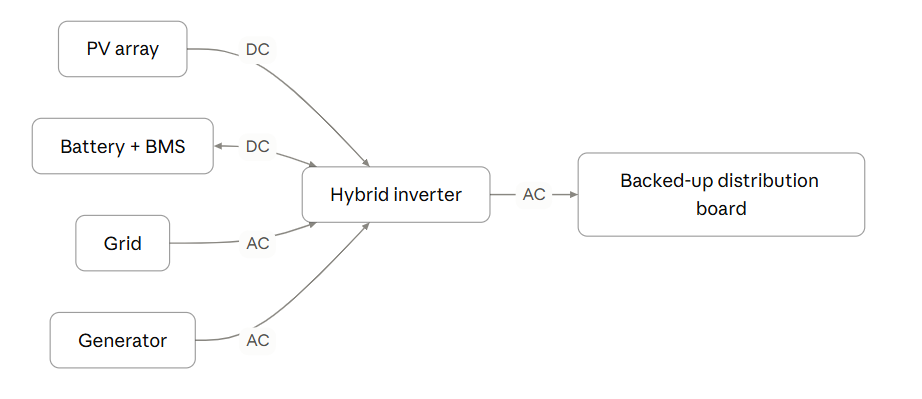
In a DC-coupled system, the PV array connects to the inverter's MPPT input and charges the battery on the DC side; this is the usual hybrid arrangement. In an AC-coupled system, a separate grid-tied PV inverter supplies AC, and a battery inverter charges the battery from AC.
3.9 Site assessment
Key points |
|---|
A design is only as reliable as the information on which it is based. |
Information should be measured and observed, not assumed. |
Defects in the existing installation must be recorded and reported. |
Area | Information required | Purpose |
|---|---|---|
Customer requirements | Loads required during outages, required duration, expected savings | Defines the design objective |
Supply | Grid availability and quality, generator size and use, single- or three-phase | Determines system type and source connection |
Loads | Appliances, ratings, hours of use, simultaneous operation (unit 3.10) | Sizes the inverter and battery |
Roof or ground area | Material, condition, structure, pitch, orientation, available area | Determines mounting method and array size |
Shading | Trees, tanks, walls, poles and adjacent buildings at different times of day | Determines array location and expected yield |
Equipment location | Dry, cool, ventilated, secure and accessible space | Protects equipment life and safety |
Cable routes | Routes and lengths between array, battery, inverter and distribution board | Determines cable sizes and voltage drop |
Existing installation | Condition of wiring, distribution boards, protective devices and earthing | Identifies hazards to be resolved |
Access | Roof access, fragile surfaces, security | Informs work-at-height planning |
In Nigeria the sun passes close to overhead, predominantly to the south, and is low in the east and west in the early morning and late afternoon. Obstructions above the array's horizon on the southern, eastern or western side will shade it at some time of day and should be recorded with photographs.
Many existing installations have missing earths, undersized cables, overloaded distribution boards or signs of overheating. Connecting a new system to an unsafe installation increases the hazard. Such defects must be recorded and reported as part of the assessment.
3.10 Load analysis
Key points |
|---|
A load analysis records each appliance's power, hours of use and starting surge. |
Electricity bills show total energy only, not timing, simultaneity or surge. |
Improving load efficiency reduces the size and cost of every component. |
A bill of 300 kWh per month indicates average consumption of about 10 kWh per day. It does not show when energy is used, which loads operate together, which have starting surges, or which are essential during outages. Where supply is unreliable, it also reflects only the energy received, not the energy required.
Load table
The following example is a small shop open from 09:00 to 17:00.
Appliance | Qty | Power each | Total power | Hours per day | Energy per day |
|---|---|---|---|---|---|
LED lights | 10 | 10 W | 100 W | 8 | 0.80 kWh |
Ceiling fans | 3 | 75 W | 225 W | 8 | 1.80 kWh |
Laptop and POS | 2 | 65 W | 130 W | 8 | 1.04 kWh |
Drinks chiller (starting surge 750 W) | 1 | 150 W | 150 W | 12 (50% duty over 24 h) | 1.80 kWh |
Television | 1 | 100 W | 100 W | 6 | 0.60 kWh |
Total | 705 W | 6.04 kWh |
Continuous power is the total of loads that may operate simultaneously: 705 W. Surge power is the continuous load with the largest motor at its starting power instead of its running power:

Motors, compressors and pumps typically draw 3 to 7 times their running power when starting. Where two motors may start simultaneously, both are included.
The customer should identify essential loads to be supplied during outages; these are normally connected to a separate backed-up distribution board and clearly labelled. Where appropriate, efficiency measures such as LED lighting, inverter-type appliances and scheduling heavy loads during daylight should be recommended to EcoStride.
3.11 System sizing
Key points |
|---|
The inverter is sized for power (kW), the battery for energy (kWh) and the array for daily energy. |
Allowances must be made for losses, depth of discharge and design margin. |
Each string must satisfy two voltage checks: hot operating voltage and cold open-circuit voltage. |
This worked example continues from unit 3.10: continuous load 705 W, surge 1,305 W, daily energy 6.04 kWh.
Step 1: Inverter
- Continuous rating with a 25% margin: 705 × 1.25 ≈ 0.9 kW
- Surge capability: at least 1.3 kW
A standard size providing capacity for future loads, such as a 3 kVA, 48 V hybrid inverter, would normally be selected.
Step 2: Battery
The customer requires the chiller to operate overnight and normal loads to run for 3 hours during a cloudy grid outage.
- Overnight chiller: 150 W × 16 h × 0.5 duty = 1.2 kWh
- Daytime loads without chiller: 555 W × 3 h = 1.67 kWh
- Energy required at the loads: 2.87 kWh
- Allowing for inverter efficiency (92%): 2.87 ÷ 0.92 = 3.12 kWh usable
- Allowing for depth of discharge (90%): 3.12 ÷ 0.90 = 3.47 kWh rated
A 51.2 V, 100 Ah LFP battery (5.12 kWh) meets the requirement with margin for ageing and growth.
Step 3: PV array
A performance factor of approximately 0.75 allows for temperature, soiling, cable and battery losses.

With 5 peak sun hours: 6.04 ÷ (5 × 0.75) ≈ 1.61 kWp, requiring at least three 550 W modules.
Step 4: String voltage
The inverter has an MPPT range of 120–450 V and a maximum PV input of 500 V. Using the module in unit 3.5, hot Vmp is approximately 41.9 × 0.86 = 36.0 V and cold Voc approximately 50.9 V per module.
Modules in series | Hot Vmp | Cold Voc | Result |
|---|---|---|---|
3 | 108 V | 153 V | Fails: below MPPT minimum |
4 | 144 V | 204 V | Passes |
9 | 324 V | 458 V | Passes |
10 | 360 V | 509 V | Fails: exceeds maximum input voltage |
The design therefore uses 4 modules (2.2 kWp). The voltage check increased the array size above the energy requirement, and the 10-module case shows that open-circuit voltage at low temperature, not operating voltage, sets the maximum string length. String current (Isc 14.0 A) must also be within the inverter's input current limit.
3.12 Cables and voltage drop
Key points |
|---|
A cable must carry its current without overheating, limit voltage drop and be protected by its overcurrent device. |
Ambient temperature, grouping and installation method reduce current-carrying capacity. |
Low-voltage, high-current circuits such as battery cables require the largest conductors. |
A cable's rated current-carrying capacity applies to reference conditions. High ambient temperatures (air beneath a roof sheet can greatly exceed 40 °C), grouping with other cables, and enclosure in conduit or insulation reduce it, in combination often by a third or more. Correction factors are given in manufacturers' tables and the applicable standards.
For DC and single-phase circuits, where current flows out and back:

where L is the one-way length (m), I the current (A), A the conductor cross-section (mm²) and ρ the resistivity of copper, approximately 0.0175 Ω·mm²/m at 20 °C.
Example 1: battery cable (48 V, 100 A, 3 m one way).
Conductor | Resistance | Voltage drop | Power loss |
|---|---|---|---|
10 mm² | 0.0105 Ω | 1.05 V (2.2%) | 105 W |
25 mm² | 0.0042 Ω | 0.42 V (0.9%) | 42 W |
Undersized battery cables waste energy as heat and reduce the voltage at the inverter, which can cause false low-battery shutdowns under load.
Example 2: PV string cable (approximately 168 V, 13.13 A, 30 m one way).
Conductor | Voltage drop | Percentage |
|---|---|---|
4 mm² | 3.4 V | 2.1% |
6 mm² | 2.3 V | 1.4% |
Designers commonly limit DC voltage drop to about 1–3%. The overcurrent device must not exceed the derated capacity of the cable (Module 2, unit 2.9), and the conductor must suit the equipment terminals.
3.13 Equipment compatibility
Key points |
|---|
A nominal voltage label is not a specification. |
Voltage ranges, current limits, chemistry, communication and manufacturer approval must all be confirmed. |
A 16-cell LFP battery is 51.2 V nominal and operates between approximately 44.8 V and 57.6 V. A 48 V lead-acid bank charges at approximately 57–58 V and floats at approximately 54 V. Equipment described as "48 V" may therefore not be compatible.
Before equipment is approved, the following must be confirmed:
Interface | Checks |
|---|---|
Battery and inverter | Overlapping voltage ranges; charge and discharge current limits; correct chemistry profile; BMS communication interface and protocol; manufacturers' compatibility approval |
Array and inverter | Hot and cold string voltage checks; string current within MPPT input limit; array power within PV input rating |
Protection | DC rating at maximum circuit voltage and correct polarity; adequate breaking capacity; RCD type as specified by the inverter manufacturer |
Equipment is not approved until every item has been confirmed.
Case studies
The following cases are based on situations commonly encountered on Nigerian sites. Names and places are illustrative.
Case 1: kVA and kWh confused. A customer in Owerri was told he had "a 5 kVA system" and expected it to supply his home overnight. The system had a 5 kVA inverter but a 2.4 kWh battery, which was exhausted by midnight. Principle: units 3.2 and 3.7.
Case 2: Motor starting. A hotel in Jos operated a 3 kW borehole pump from a 5 kVA inverter. The pump ran satisfactorily but tripped the inverter at every start, requiring approximately 12 kW momentarily. A soft starter resolved the problem. Principle: unit 3.10.
Case 3: Cold-morning overvoltage. Twelve modules with a datasheet Voc of 41 V (492 V in total) were connected to an inverter rated for 500 V maximum input. On a cold harmattan morning the string voltage exceeded 500 V and the inverter input was damaged. Principle: unit 3.11.
Relationship to performance rating
Rating measure | Relevant units |
|---|---|
Callbacks | 3.10, 3.11, 3.13 |
Quality of workmanship | 3.12, 3.13 |
Customer rating | 3.2, 3.7 (accurate expectations of system capacity) |
Reporting | 3.9 |
Practical activities
- Prepare a load table for a home or small business and calculate continuous power, surge power and daily energy.
- From a module datasheet, record Pmax, Vmp, Imp, Voc, Isc and the temperature coefficients, and calculate the output at 65 °C.
- Using the same module and any hybrid inverter datasheet, determine the minimum and maximum number of modules per string.
- Calculate the rated and usable energy of an installed battery and its runtime at 400 W.
- Measure a cable route on site and calculate the voltage drop for two conductor sizes.
- Record all potential sources of shading at a building.
Formulas
Quantity | Formula |
|---|---|
Ohm's law | V = I × R |
Power | P = V × I |
Resistive heating | P = I² × R |
Energy | E (kWh) = P (kW) × t (h) |
Battery energy | E (kWh) = V × Ah ÷ 1,000 |
Usable battery energy | Rated energy × depth of discharge |
Real power | kW = kVA × power factor |
Surge power | Other loads + largest starting load |
Array size | Daily energy ÷ (PSH × 0.75) |
Temperature correction | Value × (1 + coefficient × temperature difference) |
Voltage drop (DC or single-phase) | 2 × L × I × 0.0175 ÷ A |
Glossary
Term | Definition |
|---|---|
Apparent power (kVA) | The product of voltage and current, including the effect of power factor |
BMS | Battery management system; monitors and protects a lithium battery |
Bypass diode | A diode allowing current to pass around a shaded group of cells |
C-rate | Charge or discharge current relative to battery capacity |
Continuous power | The total power of loads that may operate simultaneously |
Depth of discharge (DoD) | The proportion of battery capacity used before recharging |
Derating | Reduction of a rating to account for operating conditions |
Irradiance | Solar power per unit area, in W/m² |
MPPT | Maximum power point tracking |
Peak sun hours (PSH) | Daily solar energy expressed as hours at 1,000 W/m² |
Power factor | The ratio of real power (kW) to apparent power (kVA) |
State of charge (SoC) | Stored energy as a percentage of capacity |
State of health (SoH) | Remaining capacity as a percentage of original capacity |
STC | Standard Test Conditions: 1,000 W/m² and 25 °C cell temperature |
Surge power | Short-duration power required to start a motor |
Temperature coefficient | Change in a parameter per °C of temperature change |
Vmp, Imp, Voc, Isc | Voltage and current at maximum power; open-circuit voltage; short-circuit current |
Voltage drop | Voltage lost along a conductor due to its resistance |
There are no comments for now.