Module 2: Safety, Protection & Technical Judgment
Module 2: Safety, Protection & Technical Judgment
24 sept. 2026
Module information | |
|---|---|
Audience | Applicants to the EcoStride Installation Partner Programme |
Study time | About 5 hours |
Units | 13 |
Assessment | Part 1, Segment 2 (10 questions) |
Prerequisites | Programme Guide; Module 1 |
Introduction
Solar and battery installations combine three significant hazards: work at height, electrical energy that cannot be fully switched off, and stored chemical energy. Serious incidents most often occur when a person assumes that equipment is safe without confirming it. This module sets out how hazards are identified and controlled, and when work must stop.
Learning outcomes
On completing this module, partners should be able to:
- Explain their duty and authority to stop unsafe work;
- Identify hazards on a solar site and select appropriate controls;
- Select and inspect PPE, tools and test instruments;
- Plan work at height safely;
- Describe how electric shock and arc flash cause injury, and respond to an electrical accident;
- Isolate all energy sources and prove a circuit dead;
- Explain why PV conductors remain live in daylight;
- Recognise dangerous battery conditions and respond correctly;
- Explain the function of protective devices and why DC circuits require DC-rated devices;
- Explain the purpose of earthing and bonding;
- Prevent backfeed from generators;
- Respond to fire and emergencies involving PV and battery systems;
- Apply the correct instructions and escalate when necessary.
2.1 Safety responsibilities
Key points |
|---|
No deadline or customer requirement justifies an unsafe act. |
Every person on site has the authority and the duty to stop unsafe work. |
Hazards must be controlled before work continues. |
Partners owe a duty of care to themselves, their team, the customer, the customer's household or staff, and members of the public. A system that functions correctly but leaves an exposed live conductor in a home has not been installed safely.
Any partner who considers work to be unsafe must stop it, explain the reason, inform EcoStride and resume only when the hazard has been controlled. Customer pressure, weather delays and schedules do not override this. Near misses should be reported, as they give warning before an injury occurs.
2.2 Hazard identification and risk assessment
Key points |
|---|
A hazard is anything that can cause harm. Risk combines the likelihood and severity of that harm. |
Risks are assessed before work starts and again whenever conditions change. |
Hazards should be eliminated where possible. PPE is the last line of defence. |
A wet metal roof is a hazard. On a low, single-storey building the risk may be moderate; on a steep two-storey roof after rain it is high, because a fall is both more likely and more likely to be fatal.
Common hazards
Hazard | Typical sources |
|---|---|
Falls | Roofs, ladders, open edges, fragile sheets and roof lights |
Electric shock | PV conductors in daylight, batteries, grid and generator supplies, damaged insulation |
Arc flash and burns | Battery short circuits; opening DC circuits under load |
Fire | Poor connections, damaged batteries, incorrect protective devices |
Chemical | Damaged or leaking batteries; battery gases |
Manual handling | Panels, inverters and batteries (lithium batteries may exceed 40–50 kg) |
Heat | Direct sun on roofs; hot metal surfaces |
Cuts and eye injury | Sheet-metal edges, drilling, cable cutting |
Falling objects | Tools and materials dropped from height |
Carbon monoxide | Generators operating near work areas or in enclosed spaces |
Hierarchy of controls
Controls should be selected in the following order of preference:
- Eliminate the hazard, for example by isolating a circuit.
- Substitute a safer method, for example by assembling components on the ground.
- Engineering controls, such as edge protection or terminal covers.
- Administrative controls, such as procedures, signage, briefings and exclusion zones.
- Personal protective equipment.
PPE is the last resort because it protects only the wearer, only when worn correctly and in good condition, and does not remove the hazard.
Risk assessment is repeated whenever conditions change: rain begins, a new person arrives, damage is discovered or a generator starts. This is known as dynamic risk assessment.
2.3 PPE, tools and test instruments
Key points |
|---|
PPE and tools are inspected before every use. Damaged items are withdrawn. |
Test instruments must be rated for the voltage and measurement category of the circuit. |
Personal protective equipment
Item | Protects against | Pre-use check |
|---|---|---|
Safety helmet | Falling objects, head impact | No cracks; within service life |
Safety footwear | Crushing, penetration, slips | Sound soles with good grip |
Insulating gloves | Electric shock | No cuts, holes or cracks; correct voltage rating |
Work gloves | Cuts from sheet metal and panel frames | Intact |
Eye protection | Debris, arc flash, battery electrolyte | Clean and unscratched |
Fall-arrest harness and lanyard | Falls from height | Webbing undamaged; buckles functional; not previously used to arrest a fall |
High-visibility clothing | Vehicle movements | Clean and visible |
Sun protection and drinking water | Heat stress | Sufficient for the working day |
Tools
Insulated hand tools should be rated to 1,000 V and in good condition. Crimping tools must match the connector and conductor being terminated. Power tools must have undamaged leads and guards in place.
Test instruments
Multimeters and testers carry a measurement category (CAT) and voltage rating, for example CAT III 1000 V. The category indicates the fault energy the instrument can withstand without failing dangerously.
Category | Typical application |
|---|---|
CAT II | Appliances and plug-in equipment |
CAT III | Distribution boards, fixed wiring, inverters, PV strings |
CAT IV | Supply-side equipment such as service cables and meters |
For PV work, instruments should be at least CAT III and rated for DC voltages above the highest string voltage, typically 1,000 V. Unrated instruments can fail explosively. Test leads must have intact insulation and shrouded probes.
2.4 Work at height
Key points |
|---|
Falls from height are among the most common causes of fatal injury in construction. |
Work at height should be minimised and properly planned. |
Work must not proceed on wet, slippery or fragile roofs without adequate controls. |
Planning
Before work at height, the partner should establish:
- which tasks can be done on the ground instead, such as rail assembly and connector crimping;
- how access will be gained safely;
- what will prevent or arrest a fall: edge protection, scaffold, or a harness attached to a secure anchor;
- whether the roof can bear the load, and where fragile areas are;
- the weather conditions, including rain, wind and heat;
- how materials will be raised without being carried up a ladder.
Ladders
- Use a ladder in good condition, rated for the user and load.
- Set it at a ratio of approximately 4 up to 1 out.
- Extend it approximately 1 m above the landing point and secure it at the top.
- Maintain three points of contact.
- Do not carry panels or heavy items up a ladder.
Roofs
- Metal roofs are extremely slippery when wet, dusty or covered in dew.
- Roof lights, translucent sheets, old asbestos-cement sheets and corroded metal may not bear a person's weight. Walk only along lines of fixings over the supporting structure.
- Panels act as sails in wind. Panel handling should stop in strong wind.
- Metal roofs in afternoon sun can cause burns and heat exhaustion.
- The area beneath the roof edge must be kept clear of people.
Where the roof is wet, the wind is strong, there is no suitable anchor or the correct equipment is not available, roof work must stop. The reason should be explained to the customer and EcoStride and the work rescheduled.
2.5 Electric shock and arc flash
Key points |
|---|
Injury is caused by current passing through the body, and small currents can be fatal. |
DC is not inherently safer than AC. |
A casualty still in contact with a live conductor must not be touched. |
Effects of current
Current flows through the body when it bridges two points at different voltages. Wet skin and damp ground greatly reduce the body's resistance and increase the current.
AC current through the body (approximate) | Effect |
|---|---|
1 mA | Perception |
10–15 mA | Muscular contraction; the person may be unable to let go |
30 mA | Breathing difficulties. RCDs for personal protection operate at this level. |
50–100 mA and above | Ventricular fibrillation, which is fatal without prompt treatment |
DC produces different muscular effects but can still cause serious burns and cardiac injury. DC voltages above approximately 120 V are treated as hazardous. PV strings commonly operate at 300–600 V DC, and batteries can deliver thousands of amperes into a short circuit.
Arc flash
An arc is a current flowing through air. It can occur when a circuit is opened under load or when a tool or loose conductor bridges two conductors. Arc temperatures can reach several thousand degrees, causing severe burns, eye injury and molten-metal spatter. Because DC current does not pass through zero as AC does 100 times a second at 50 Hz, a DC arc is harder to extinguish. Common causes include a tool bridging battery terminals, disconnecting PV connectors under load, and using switches or breakers not rated for DC.
Response to an electrical accident
- Do not touch the casualty if they may still be in contact with the source.
- Switch off the supply if this can be done quickly and safely. Otherwise, separate the casualty from the source using a dry, non-conductive object.
- Call for help.
- If the casualty is not breathing normally, begin CPR if trained.
- Cool burns with clean water and cover them loosely.
- Ensure the casualty receives hospital assessment, even if they appear unharmed.
- Report the incident to EcoStride immediately.
All partners should hold current first aid and CPR training.
2.6 Safe isolation
Key points |
|---|
A hybrid system may have up to four sources: PV, battery, grid and generator. |
A blank display is not evidence of isolation. |
Isolate, lock off, and prove dead with a tester that is itself proved before and after use. |
In a hybrid system, energy may be supplied by the PV array (whenever light is present), the battery (continuously), the grid, and a generator that may start automatically. Inverter capacitors also retain charge for a period after shutdown. Switching off an inverter normally disables its display but does not disconnect these sources.
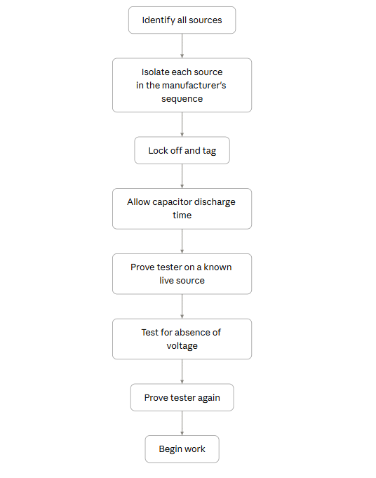
The tester is proved before and after testing because a faulty tester, with a flat battery or broken lead, will indicate zero on a live circuit. Locks and tags prevent the circuit being re-energised by another person or by automatic equipment. Insulating gloves provide additional protection but do not replace isolation.
2.7 PV-specific hazards
Key points |
|---|
PV modules generate voltage whenever they are exposed to light. They cannot be switched off. |
An isolator makes safe only the circuit on its load side. |
PV connectors must not be separated while current is flowing. |
Module voltage remains high even in low light; it is the current that falls. Modules connected in series add their voltages: ten modules with an open-circuit voltage of about 45 V each produce around 450 V DC.
Opening the PV isolator makes the inverter side safe to work on once proved dead, but the conductors between the modules and the isolator remain live. Switching off the grid, the battery or the inverter has no effect on them. When working on the array side, partners should treat all conductors as live, work in low light or cover the modules with opaque material where practicable, stop the current by opening the isolator before disconnecting connectors, and test before touching.
Other PV hazards include:
- earth faults, where damaged insulation energises frames or rails;
- hot spots, where shaded, cracked or soiled cells overheat;
- firefighting difficulties, since roof-mounted arrays cannot be switched off, which makes clear labelling essential;
- broken modules, which continue to generate.
2.8 Battery safety
Key points |
|---|
Batteries are permanently live and can deliver very high short-circuit currents. |
Lead-acid batteries release explosive hydrogen and contain corrosive acid. |
Heat, swelling, smoke or a chemical odour from a lithium battery indicates an emergency. |
A battery cannot be switched off. If a spanner bridges its terminals, the resulting current can heat the tool to red heat, weld it in place and cause burns and fire within a second.
Handling precautions
- Remove rings, watches and other metal jewellery.
- Use insulated tools.
- Keep terminal covers in place except when making a connection.
- Connect and disconnect one terminal at a time, in the sequence the manufacturer specifies.
- Never place tools or metal objects on a battery.
- Use correct lifting techniques and assistance.
Lead-acid batteries
Charging releases hydrogen, which is explosive in air. Battery areas require ventilation and must be free of flames, smoking and sparks. The electrolyte is sulphuric acid, which requires eye and hand protection and access to clean water for washing.
Lithium batteries and thermal runaway
Most modern stationary batteries use lithium iron phosphate (LFP) chemistry. LFP is more stable than other lithium chemistries but can still fail dangerously through thermal runaway: a self-sustaining reaction in which a damaged cell overheats, releases flammable and potentially toxic gases, and heats neighbouring cells.
Causes include overcharging, charging after excessive discharge, physical damage, short circuit, high temperature and manufacturing defects.
Warning signs are abnormal heat, swelling, hissing, leakage, smoke or a sweet or chemical odour. On observing any of these, the partner should:
- stop work and not touch, move or open the battery;
- evacuate the area and keep people away;
- isolate the battery only if this can be done safely, remotely and with authority;
- call the fire service if smoke or fire is present;
- report to EcoStride immediately by telephone.
The system must not be restarted, a swollen module must not be opened, and fans must not be used, as they disperse the gas and supply oxygen. Damaged or swollen batteries must never be reused, charged or stored indoors.
2.9 Protective devices
Key points |
|---|
Overcurrent devices protect the cable from overheating. |
AC-rated devices must not be assumed suitable for DC circuits. |
Repeated tripping indicates a fault to be investigated, not a device to be replaced. |
Device | Function |
|---|---|
Fuse | Interrupts overload and short-circuit current by melting a link; must be replaced after operation |
MCB | Interrupts overload (thermal element) and short-circuit current (magnetic element); resettable |
MCCB | As MCB, for higher currents; often adjustable |
RCD / RCCB | Detects current leaking to earth and disconnects the supply; 30 mA devices provide personal protection |
RCBO | Combined MCB and RCD |
SPD | Diverts transient overvoltages from lightning and switching to earth |
Switch-disconnector (isolator) | Provides safe isolation; must be DC-rated on PV and battery circuits |
Protection of cables
Each cable has a maximum safe current. The overcurrent device is selected so that it operates before that current is exceeded:
Design current ≤ device rating ≤ cable current-carrying capacity
Replacing a tripping breaker with a larger one allows the cable to overheat. The cause must be identified first: overload, short circuit, faulty appliance, loose connection or undersized cable.
DC devices
Because DC current does not pass through zero, a DC-rated device incorporates arc-extinguishing features that AC-only devices may lack. DC devices must be checked for:
- DC voltage rating, exceeding the maximum circuit voltage (for PV strings, the maximum open-circuit voltage);
- current rating;
- polarity, as many DC devices are polarised;
- breaking capacity, the maximum fault current the device can safely interrupt.
Omitting protection on the grounds that the inverter has internal protection leaves the external cables unprotected.
RCD types
RCDs are classified by the types of leakage current they detect (AC, A, F, B). Some inverters can produce leakage currents that Type AC devices do not detect. The type specified by the inverter manufacturer must be used.
2.10 Earthing, bonding and lightning protection
Key points |
|---|
Earthing provides a path for fault current so that protective devices operate. |
A system operates normally without its earth, so a missing earth is not apparent until a fault occurs. |
Bonding keeps exposed metal parts at the same potential. |
If a live conductor contacts an earthed metal enclosure, fault current flows through the earth conductor and the protective device disconnects the supply. Without an earth, the enclosure remains live at a dangerous voltage while the system continues to operate normally. For this reason, a system must never be commissioned without its protective earth. Warnings to the customer, waivers or operation in battery mode do not make exposed metal safe.
Earthing arrangements
In many Nigerian buildings the supply does not provide a reliable earth, and the installation depends on its own earth electrode. This is known as a TT system. In a TT system the earth electrode resistance must be low enough for the RCD to operate reliably, and it must therefore be measured.
Bonding
Panel frames, mounting rails, the metal enclosures of inverters, batteries and distribution boards, and metal cable containment must be bonded to earth.
Lightning and surges
Lightning need not strike a building to cause damage; nearby strikes induce surges in long conductors such as PV cables and supply cables. Protection measures include:
- SPDs on the PV input and AC side, and where specified on the battery side;
- running positive and negative PV conductors together to minimise loop area;
- coordinating the PV installation with any structural lightning protection system.
Work on roofs or external cables must not be carried out during thunderstorms.
2.11 Generators, the grid and backfeed
Key points |
|---|
Two supply sources must never be connected together except through equipment designed for the purpose. |
Backfeed endangers line workers remote from the site. |
Generators produce carbon monoxide, which is colourless and odourless. |
Backfeed occurs when power flows from a building into the supply network. If a generator supplies a building still connected to the grid, the distribution transformer steps the generator's 230 V up to the line voltage (11 kV or 33 kV), energising lines that DisCo staff may believe to be dead.
Connecting a generator to a building through a lead with a plug at each end is prohibited. The pins of the free plug are live while the generator runs, the building's protective devices are bypassed, and backfeed occurs whenever the main switch is closed. Opening the main switch beforehand or obtaining a customer waiver does not make this arrangement acceptable.
Generators must be connected only through:
- a changeover switch, which connects the load to one source at a time;
- an automatic transfer switch with an interlock preventing simultaneous connection; or
- the inverter's dedicated generator input, where provided.
Joining two unsynchronised AC supplies produces an effective short circuit, with risk of explosion, fire and equipment damage.
Generators must not be operated indoors, in garages, or near windows or air intakes. Persons experiencing headache, dizziness or nausea near a generator should be moved to fresh air immediately.
2.12 Fire and emergency response
Key points |
|---|
Exits, isolation points and extinguishers should be identified before work begins. |
Water must not be used on live electrical equipment. |
The safety of people takes priority over property. |
Before starting work, partners should identify escape routes, every isolation point (PV, battery, AC and generator), the nearest suitable extinguisher, local emergency numbers and the route to the nearest hospital.
Extinguisher | Suitable for | Not suitable for |
|---|---|---|
CO₂ | Electrical equipment | Large outdoor fires |
Dry powder | Electrical and most other fires | Confined spaces |
Water or foam | Wood, paper and textiles | Live electrical equipment |
In the event of fire:
- raise the alarm and evacuate;
- call the fire service;
- isolate supplies only if safe to do so;
- tackle the fire only if it is small, the correct extinguisher is available and an escape route is maintained;
- inform the fire service that the installation includes PV modules, which remain live, and batteries, which may reignite;
- report to EcoStride by telephone.
Lithium battery fires are difficult to extinguish and may reignite hours later. They should be left to the fire service.
2.13 Technical judgment and escalation
Key points |
|---|
The applicable instructions are those for the exact model installed. |
Stopping to seek advice is a professional decision. |
Equipment differs between manufacturers and between models. Shutdown and start-up sequences, settings, torque values and clearances are specific to each product. Where the manufacturer's instructions differ from a partner's usual practice, the instructions take precedence. Where it is unclear which instructions apply, the partner should confirm them from the correct manual or with EcoStride technical support before proceeding.
Partners should stop and seek advice when:
- the equipment, fault or alarm is unfamiliar;
- site conditions do not match the design;
- the task requires skills, tools or authority the partner does not have;
- there is pressure to omit a step.
An escalation should include what the partner was doing, what was found, model numbers, alarm codes, readings, photographs and the checks already made. It should be sent by WhatsApp, or by telephone where there is an urgent safety concern.
Case studies
The following cases are based on situations commonly encountered on Nigerian sites. Names and places are illustrative.
Case 1: Incomplete isolation. A technician in Port Harcourt switched off an inverter to replace an AC breaker and began work when the display went blank. The battery remained connected, and the inverter output was restored when the power button was knocked. The technician received a severe shock. Principle: unit 2.6.
Case 2: Wet roof. A crew in Ibadan, behind schedule, sent a team member onto a wet metal roof after a storm. He slipped towards the edge and was stopped only by a gutter bracket. Principle: units 2.1 and 2.4.
Case 3: Upsized breaker. A 20 A breaker that tripped repeatedly in a Kano shop was replaced with a 32 A breaker. The underlying cause, a loose neutral connection, later overheated and caused a fire in the ceiling. Principle: unit 2.9.
Case 4: Swollen battery. During a maintenance visit in Abuja, a partner found a warm, slightly swollen battery module. He refused the customer's request to restart the system, cleared the room and reported to EcoStride. An internal cell defect was later confirmed. Principle: unit 2.8.
Relationship to performance rating
Rating measure | Relevant units |
|---|---|
Safety-critical conduct | 2.4, 2.6, 2.9, 2.10: serious breaches are reviewed individually and are not offset by other scores |
Quality of workmanship | 2.9, 2.10 |
Callbacks | 2.9, 2.10 |
Reporting | 2.1, 2.13 |
Practical activities
- Inspect a building with an electrical or solar installation and list at least eight hazards, with a control for each selected from the hierarchy of controls.
- At an accessible hybrid system, identify every energy source and isolation point without operating any of them.
- Practise the prove–test–prove sequence on a known live source.
- Inspect your own PPE and tools against the checklist in unit 2.3.
- Record the current, voltage, AC/DC rating and breaking capacity of three protective devices.
- Set up a ladder at the correct angle and projection, and have it checked by a colleague.
Glossary
Term | Definition |
|---|---|
Arc | Electric current flowing through air, producing intense heat and light |
Backfeed | Flow of power from a building into the supply network |
Bonding | Connection of metal parts so that they remain at the same potential |
Breaking capacity | The maximum fault current a protective device can safely interrupt |
Changeover switch / ATS | A switch that connects a load to one supply source at a time |
Earthing | Connection of metal parts to earth so that fault current operates the protective device |
Hazard | Anything with the potential to cause harm |
Hierarchy of controls | The order of preference for risk controls: eliminate, substitute, engineer, administrative, PPE |
Isolation | Disconnection of a circuit from all sources of energy |
Lock-off | Securing an isolator in the off position |
Open-circuit voltage (Voc) | The voltage of a module or string when no current flows |
Prove dead | Confirm the absence of voltage using a tester proved before and after use |
RCD | A device that disconnects the supply when current leaks to earth |
Risk | The combination of the likelihood and severity of harm |
SPD | A device that diverts transient overvoltages to earth |
Thermal runaway | A self-sustaining overheating reaction in a battery cell |
There are no comments for now.